What does the image of a black hole's neighborhood look like?
Geodesic Lines in Schwarzschild and Kerr Metric
The program developed in the scope of this work visualizes light deflection effects resulting from general relativity.
Apart of the Schwarzschild metric, also the Kerr metric is implemented, because black holes in nature will always retain some angular momentum from the collapse which formed them. In addition to the gravitational lensing effect on the accretion disk, also the observed spectral flux from the accretion disk is simulated by the program. As a first approximation, the spectral flux can be calculated from the standard accretion model under the assumption of local blackbody radiation and integration over the whole disk.
This results in a multitemperature blackbody spectrum. The simulation of the spectrum is important because it is not possible yet to resolve images from real accretion disks, so only the spectra of accretion disks can be analyzed. Furthermore, the core code of the geodesic integration has been used for visualizing the run of geodesic lines. Beside using the already implementend metrics, the object oriented structure of the programs written in C++ and using external routines of the Gnu Scientific Library (GSL) permits to implement other metrics or integrators in a straight forward manner. Geodesic lines in Schwarzschild and Kerr metric
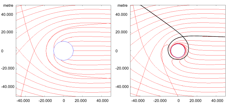
fig. 1: left: Schwarzschild metric
right: Kerr metric
M = 3.5 Mº, Kerr parameter a/M = 0.9
Comparison of Euclidean and curved spacetime raytracing

fig. 2a: Euclidean raytracing
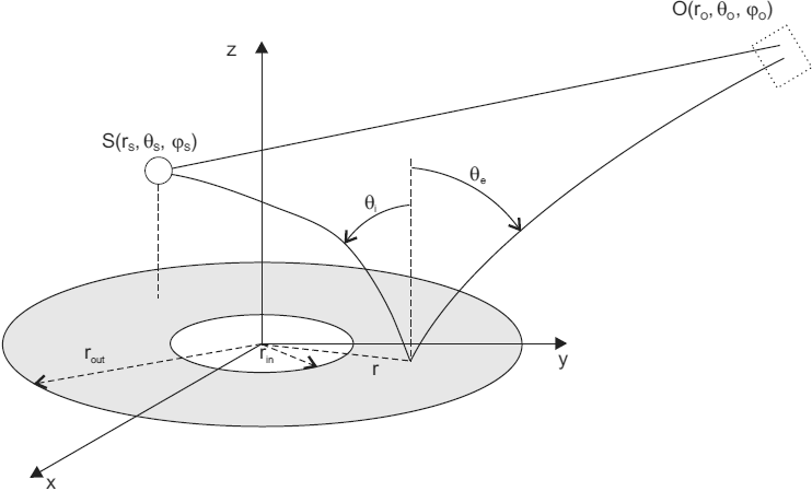
fig. 2b: curved spacetime raytracing in neighborhood of a black hole
light comes from primary source S is reflected at the surface of the accretion disk and is re-emitted to observer O
The following images show accretion disks in Schwarzschild and Kerr metric under various inclination angles. Colors refer to temperature from calculated spectra. Lensing effects are striking.
M = 3.5 Mº, Kerr parameter a/M = 0.9
| inclination angle | Schwarzschild metric | Kerr metric | ||
|---|---|---|---|---|
| 1° | 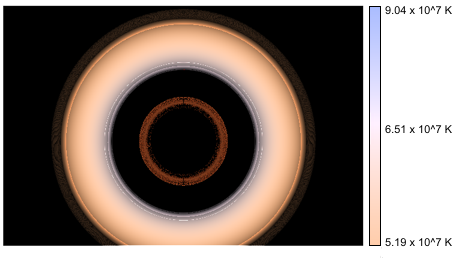 | 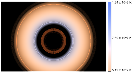 | ||
| 30° | 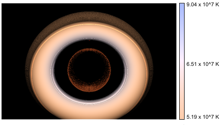 | 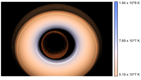 | ||
| 60° | 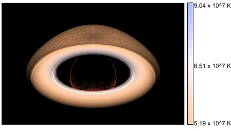 | 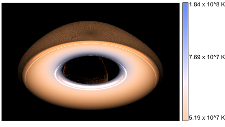 | ||
| 85° | 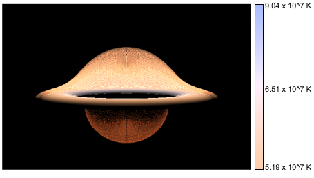 | 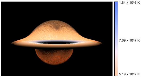 |
prograd and retrograd rotation

fig. 3: accretion disk under inclination of 85 degree, M=7 Mº
left: Kerr parameter a/M = 0.9 (prograd)
right: Kerr parameter a/M = -0.9 (retrograd)
increasing mass...
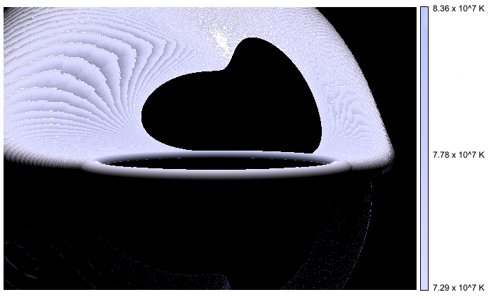
fig. 4: accretion disk under inclination of 85 degree, M=17 Mº, Kerr parameter a/M = 0.9
outer radius of accretion disk is well beyond the marginal stable orbit being the inner radius
A short introduction into methodology is available at bsc_thesis_gr_raytracing.pdf
Bachelor thesis and source code are available on request.